Build a 12V To 24V DC DC Converter Circuit Diagram


Build a 12V To 24V DC-DC Converter Circuit Diagram.This simple 12V To 24V DC-DC Converter Circuit Diagram can provide up to 24V from a 12V source. It can be used to run radios, small lights, relays, horns and other 24V accessories from a 12V vehicle with a maximum draw of about 800mA. 

It can be used to charge one 12V battery from another, or step up the voltage just enough to provide necessary overhead for a 12V linear regulator. Using one op-amp as a square wave oscillator to ring an inductor and another op-amp in a feedback loop, it won't drift around under varying loads, providing a stable 24V source for many applications. With a wide adjustment in output this circuit has many uses.

 12V To 24V DC-DC Converter Circuit Diagram
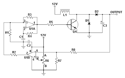
12V To 24V DC-DC Converter Circuit Diagram

Parts

Part
Total Qty.
Description
Substitutions
R1, R2, R3, R4, R8, R76100K 1/4W Resistor
R51470 Ohm 1/2W Resistor
R6110K Linear Pot
C110.01uF Mylar Capacitor
C210.1uF Ceramic Disc Capacitor
C31470uF 63V Electrolytic Capacitor
D111N4004 Rectifier Diode
D21BY229-400 Fast Recovery DiodeSee Notes
Q11BC337 NPN Power Transistor
U11LM358 Dual Op Amp IC
L11See Notes
MISC1Board, Wire, Socket For U1, Case, Knob For R6, Heatsink for Q1

Notes

  • R6 sets the output voltage. This can be calculated by Vout = 12 x (R8/(R8+R7)) x (R6B/R6A).
  • L1 is made by winding 60 turns of 0.63MM magnet wire on a toroidial core measuring 15MM (OD) by 8MM (ID) by 6MM (H).
  • D2 can be any fast recovery diode rated at greater then 100V at 5A. It is very important that the diode be fast recovery and not a standard rectifier.
  • Q1 will need a heatsink.


Sourced By Circuitsstream

Comments

Popular posts from this blog

Power Amplifier with voltage regulator 4 × 50 Watt TDA8588

Power Amplifier with voltage regulator 4 × 50 Watt TDA8588    The TDA8588 is a multiple voltage regulator combined with four independent audio power amplifiers configured in bridge tied load with diagnostic capability. The output voltages of all regulators except regulators 2 and 3 can be controlled via the I2C-bus. However, regulator 3 can be set to 0 V via the I2C-bus. The output voltage of regulator 2 (microcontroller supply) and the maximum output voltage of regulator 3 (mechanical digital and microcontroller supplies) can both be either 5 V or 3.3 V depending on the type number. The maximum output voltages of both regulators are fixed to avoid any risk of damaging the microcontroller that may occur during a disturbance of the I 2C-bus. The amplifier diagnostic functions give information about output offset, load, or short-circuit. Diagnostic functions are controlled via the I2C-bus. The TDA8588 is protected against short-circuit, over-temperature, open ground and open VP connectio

PIC16F887 877 programming in C Tutorial 5 LCD Interfacing

LCD Interfacing: In this tutorial i will show you how to interface 16x2 LCD with micro-controller. 16x2 means there are two rows and each row contain maximum 16 characters.  For more detail refer to the LCD datasheet, which you are using. Basic Connection: Applies 5v to pin 2 and gnd to pins 1 & 5. Use variable resistor at pin 3 to set contrast. Pins 7 to 14 are the data pins,, used to send/rec data. Pin 6 is of enable; every time when you write to lcd you should have to give high to low, to this pin. pin 4 is register select pin use to give commands like clear, home etc.   In this tutorial i will interface lcd in 4-bit instead of 8-bit, so we only required four data pins. Code: Lets write a code that will display the motor status and its direction; it will be fun!!!! Requirements: Design a motor controller circuit using l298 and display its status on lcd. LCD is connected to portb and motor controller circuit is at portd. Required two switches to change motor direction; if both ar

12V to 30V DC to DC Converter circuit Diagram

 12V to +/- 30V DC to DC Converter circuit Diagram This is a DC to DC converter for car power amplifier. 12V input generates +30V and -30V output for preamp or power amplifiers. Circuit uses SG3525 IC, Mosfets and switching power supply.