
5V DC Regulated Power Supply with Short Circuit Protection


                                           5vdc power supply circuit diagram featured short circuit protection
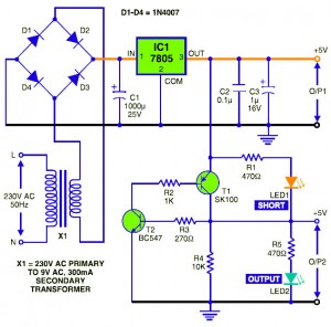
This is the circuit diagram of 5V DC regulated power supply which featured with short circuit protection system. There are 2 kind of output that are regulated 5V DC with short circuit protection and without circuit protection. The main circuit is protected from any damage due to short-circuit in the additional power supply circuit by cutting off the derived supply voltage. The derived supply voltage restores automatically when shorting is removed. An indicator LED is utilized to show whether short-circuit exists or not.

Power Supply Block:
This circuit works just like the ordinary DC power supply adapter, in the main power supply circuit, 230V AC from main home electric source is stepped down by transformer X1 (230V AC primary to 0-9V, 300mA secondary), then rectified by a fullwave rectifier comprising diodes D1 through D4 with bridge arrangement (you may use a single bridge diode), filtered by capacitor C1 and regulated by IC 7805 to give regulated 5V DC output (O/P1).
Short-Circuit Protection Block:
Transistors SK100 and BC547 are used to derive the secondary output of around 5V (O/P2) from the main 5V supply (O/P1).
The working of this circuit is quite simple. When the 5V DC output from regulator IC 7805 is available, transistor BC547 conducts through resistors R1 and R3 and LED1. As a result, transistor SK100 conducts and short-circuit protected 5V DC output appears across O/P2 terminals. The green LED (LED2)  lows to indicate the same, while the red LED (LED1) remains off due to the presence of the same voltage at both of its ends.
When O/P2 terminals short, BC547 cuts off due to grounding of its base. As a result, SK100 is also cut-off. Thus during short-circuit, the green LED (LED2) turns off and the red LED (LED1) glows. Capacitors C2 and C3 across the main 5V output (O/P1) absorb the voltage fluctuations occurring due to short-circuit in O/P2, ensuring disturbance-free O/P1. The design of the circuit is refer to the relationship given below:
RB = (HFE × VS) / (1.3 × IL)
where,
RB = Base resistances of transistors of SK100 and BC547
HFE = 200 for SK100 and 350 for BC547
Switching Voltage VS = 5V
1.3 = Safety factor
IL = Collector-emitter current of transistors
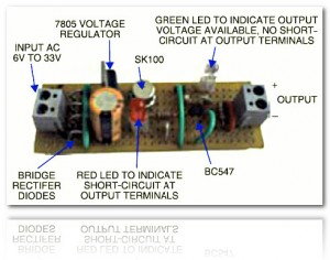
Build the circuit on a general purpose PCB and mount in a general circuit box. Connect O/P1 and O/P2 terminals on the front panel of the cabinet. Also connect the mains power cord to feed 230V AC to the transformer. Connect LED1 and LED2 for visual indication.
This circuit has been tested by the author, the circuit that already built is shown on the following image:
                                 powersupply circuit with shortcircuit protection


Read more http://circuitdiagram.net/5v-dc-regulated-power-supply-with-short-circuit-protection.html

Comments

Popular posts from this blog

Electronic Extended Play Circuit Diagram

This is a Electronic Extended Play Circuit Diagram. A single op amp-one of four contained in the popular LM324-is operating in a variable pulse width, free-running square wave oscillator circuit, with its timed output driving two transistors that control the on/ off cycle of the tape-drive motor. The Oscillator` s positive feedback path holds the secret to the successful operation of the variable on/ off timing signal.   Electronic Extended Play Circuit Diagram The two diodes and pulse width potentiometer R8 allows the setting of the on and off time, without affecting the oscillator`s operating frequency. One diode allows only the discharge current to flow through it and the section of R8 that it`s connected to. The other diode, and its portion of R8, sets the charge time for the timing capacitor, C3. Since the recorder`s speed is controlled by the precise off/on timing of the oscillator, a simple voltage-regulator circuit (Ql, R3, and D4) is included.  Connecting the spe...

Power Amplifier with voltage regulator 4 × 50 Watt TDA8588

Power Amplifier with voltage regulator 4 × 50 Watt TDA8588    The TDA8588 is a multiple voltage regulator combined with four independent audio power amplifiers configured in bridge tied load with diagnostic capability. The output voltages of all regulators except regulators 2 and 3 can be controlled via the I2C-bus. However, regulator 3 can be set to 0 V via the I2C-bus. The output voltage of regulator 2 (microcontroller supply) and the maximum output voltage of regulator 3 (mechanical digital and microcontroller supplies) can both be either 5 V or 3.3 V depending on the type number. The maximum output voltages of both regulators are fixed to avoid any risk of damaging the microcontroller that may occur during a disturbance of the I 2C-bus. The amplifier diagnostic functions give information about output offset, load, or short-circuit. Diagnostic functions are controlled via the I2C-bus. The TDA8588 is protected against short-circuit, over-temperature, open ground and open VP ...

Digital Voltmeter Circuit with ICL7107

Description. The circuit given here is of a very useful and accurate digital voltmeter with LED display using the ICL7107 from Intersil. The ICL7107 is a high performance, low power, 3.5 digit analog to digital converter. The IC includes internal circuitry for seven segment decoders, display drivers, reference voltage source and a clock. The power dissipation is less than 10mW and the display stability is very high. The working of this electronic circuit is very simple. The voltage to be measured is converted into a digital equivalent by the ADC inside the IC and then this digital equivalent is decoded to the seven segment format and then displayed. The ADC used in ICL7107 is dual slope type ADC. The process taking place inside our ADC can be stated as follows. For a fixed period of time the voltage to be measured is integrated to obtain a ramp at the output of the integrator. Then a known reference voltage of opposite polarity is applied to the input of the integrator and allowed to r...